Arduinos are some of the most versatile boards you can buy. They are easy to program and use, and they get the job done for many low power low performance problems. In this tutorial, I will be showing you how PWM is used to control motors, and how you can implement it to control one with an Arduino.
Understanding PWM
PWM, or Pulse Width Modulation, is a very common form of digital signal used for various purposes. Has 2 main components, the frequency and the length.
Frequency
The frequency of a PWM signal is a representation of how long each pulse is. Take this signal for example:

Here we can see that the PWM signal rises at the same time after one full cycle. The length of this cycle is known as the frequency (marked as period in the image). To convert this frequency into time, we follow the simple formula T = 1/f. So for example, a pulse with a frequency of 20hz would last 0.05 seconds from the start of one pulse, to the start of the next.
Length
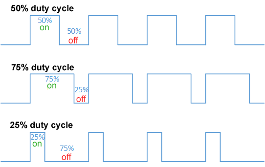
The length of a PWM signal is measured by how much percent of a single pulse is “up.” Take this image for example:

Here we can see 3 different signals. In all 3 of them, the frequency stays the same as we can see that each pulse starts at the exact same time, but the length is different. Now that we understand PWM, we can move to understanding how it works in motors.
Motor Control with PWM
Many different things use PWM, but we are trying to control a motor with it. We are going to be focusing on the common 3 wire servo motors in this tutorial. These motors generally operate at a frequency of 50hz, but you should probably check for your specific motor before assuming. We will also be using 180 degrees motors, but this should work for 270 degrees or even continuous ones.
Pulse Range
In motor control, the motor reads a “range” of PWM values and these are each a specific speed or angle depending on if you are using continuous or degree motors. This is easier to explain with an example so here is what I mean:
Here we can see 3 different pulses at a frequency of 50hz. In angular motors, a 1ms pulse means to go the the minimum angle, a 2ms pulse means to go to the maximum angle, and any length in between represents a different length. In continuous motors this represents speed rather than angle. This implementation makes it very straightforward to control a motor with PWM. Next we will go to what you have all been waiting for, how we can program an Arduino to do this.
Implementation on an Arduino
Finally, after learning about PWM, we are going to learn how to do this on an Arduino! The first step is to set up the wiring.
Wiring
The wiring for a motor and an Arduino is relatively straightforward. First you need to connect the power, so connect the black wire to ground and the red one to the correct voltage. Make sure you check the voltage of your motor before connecting it so you don’t burn it. After this, you need to identify which pins support PWM. On an Arduino Uno they are usually marked with a ~ next to the pin number. So connect your third wire to this pin and note down the number.
Servo Library
If you know anything about Arduino programming, you will probably want to try creating the pulses manually using delays and setting the pin from high to low. The problem with this implementation is that the pulses have to be super precise, and the digitalWrite function, or even the delay function take more time than they say, so the pulse ends up being very inaccurate. One way to get around this is to directly edit the register. This would work, but why do that when we can use a library provided by Arduino just for this purpose! So head over to Tools -> Library Manager -> Servo in the Arduino IDE and install the latest version. This library has a couple of functions for controlling motors, but the most important ones are attach and writeMicroseconds. Attach sets what pin the PWM wire is connected to. writeMicroseconds sets how long each pulse is “up” (keep in mind that the frequency is 50hz by default with this library). These both together create a really simple implementation to control motors. Here is an example:
Servo myservo;

void setup()
{
     myservo.attach(9);
}

void loop()
{
    myservo.writeMicroseconds(1500);
}
This example shows just how simple it is to control a motor with this library. Now you can basically write any number between 1500 and 2000 and it will turn to the corresponding angle (or spin at that speed).
Conclusion
Being able to control servos with an Arduino opens up many possibilities for projects. I hope you learned something from this article. If you have any questions, suggestions, or comments, please feel free to comment down below. If not, I’ll see you next time.
Leave a Reply